RS Flip-Flop Circuit
A flip-flop circuit is a circuit that has the ability to store past inputs and reflect them in the output.
There are various types of flip-flops depending on their structure and function. In this section, I will explain the RS type, which is a typical example.
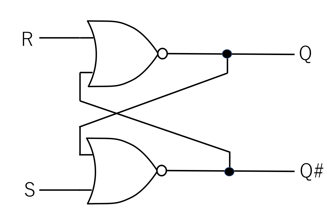
Circuit Symbol
The RS flip-flop circuit has the appearance of two NOR circuits side by side, with one of the inputs of each connected to the output portion of the other NOR, crossing each other, as shown in the circuit diagram in the figure.
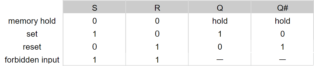
Truth Table
Now, let's look at the operation of the RS circuit based on the table on the right. First, let's consider the case where the input is S:High and R:Low. First, the High input from S goes to the NOR circuit, so the output of Q# goes Low. Next, since the output of Q# is now low, the high input that used to go to Q is no longer there, and the NOR circuit inverts it to make the output of Q high. And since the output of Q goes into the NOR circuit on the S side, the output is maintained from the previous time even when S is set low. Also, it is prohibited to set S and R to High.
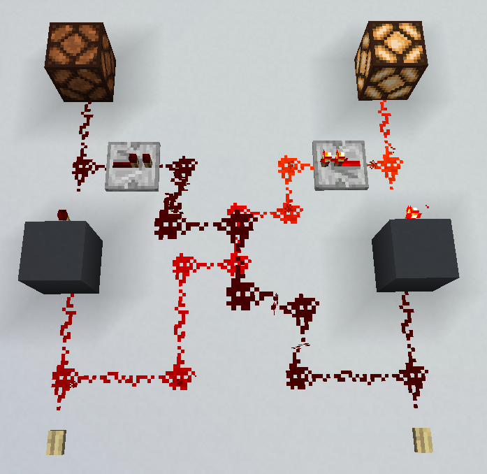
Logic circuits made in Minecraft
The RS circuit made in Minecraft looks like this. The button corresponds to the input and the lamp corresponds to the output.